
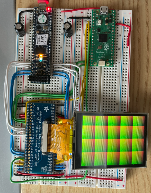
In this project, I used a breadboardable FPGA board (Cmod A7-35T) and wrote a design in Verilog that controls an ILI9341-based TFT LCD panel. In addition, I used a Raspberry Pi Pico to initialize the display. This was one of my first FPGA projects, and overall I learned a lot, but looking back on it, there were some mistakes made 😉. There were a few inferred latches, timing issues, etc., but you know what, it worked. Below shows a picture of the circuit I made to drive the display:
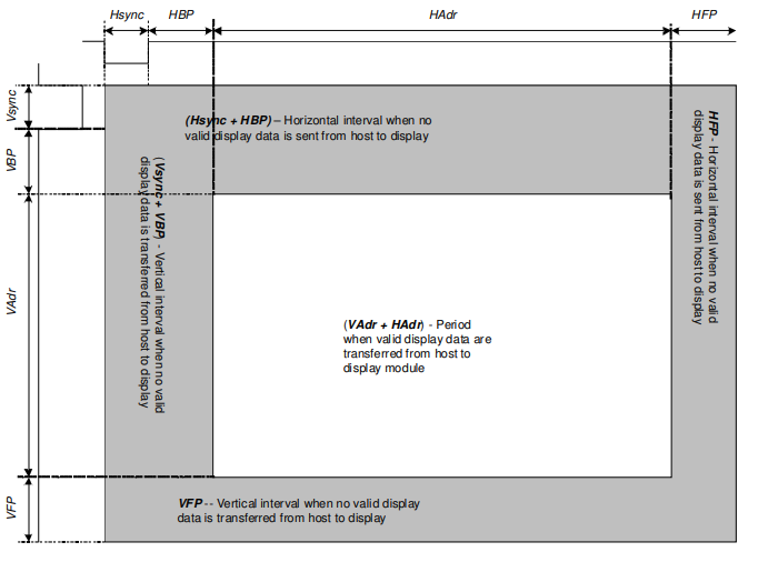
Also, for more info, one of the inspirations of using an FPGA for this project was my goal to ‘bypass’ the ILI9341 chip. See, there was a way to configure it where you could input the pixel clock and timing signals pixel by pixel (“dot clock mode”), instead of the normal method of writing to the internal framebuffer. The photo below shows the different timing regions of each frame, so essentially the hardware would have to assert HSync and VSync for certain rows/columns and could only transmit pixel data during others.
I wanted to figure out how to do that, so I set forth on it. I originally tried to use a Raspberry Pi Pico to drive the display in dot clock mode, but after trying several methods (including the Pico’s PIOs, which were interesting to learn about), it came up short. So, I decided to implement it with an FPGA.
Demo
Below shows a short recording of the display where I have my FPGA design cycle through all of the characters it supports displaying.